
Fichier:Inductively coupled crystal radio circuit.svg

Taille de cet aperçu PNG pour ce fichier SVG : 722 × 435 pixels. Autres résolutions : 320 × 193 pixels | 640 × 386 pixels | 1 024 × 617 pixels | 1 280 × 771 pixels | 2 560 × 1 542 pixels.
Fichier d’origine (Fichier SVG, nominalement de 722 × 435 pixels, taille : 36 kio)
Ce fichier et sa description proviennent de Wikimedia Commons.
Description
| Description |
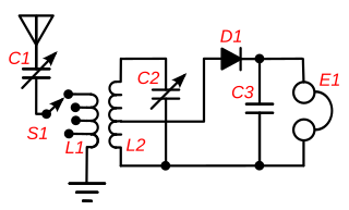
English: A circuit of an inductively-coupled crystal radio receiver with impedance matching. This type of circuit, called a "two circuit" or "loose coupler" receiver, was used in most sophisticated crystal receivers from the wireless telegraphy era which ended in the 1920s, until today. Instead of a single tuning coil, it has an antenna coupling transformer (L1,L2) which improves the poor selectivity found in most crystal receivers. Each coil functions as a tuned circuit; the primary L1 resonating with the capacitance of the antenna and the primary tuning capacitor C1 and the secondary resonating with the secondary tuning capacitor C2. The two tuned circuits interact, resulting in a much narrower bandwidth (higher Q) than a single tuned circuit when the two coils are loosely coupled. However looser coupling also reduces the amount of signal getting through the transformer. So the coupling was made adjustable. When interference was encountered the coils were separated to sharpen the bandwidth and reject the interference. Adjustable antenna matching is provided by attaching the antenna to a tap on L1 which can be selected by switch S1. This maximizes the power transferred from the antenna to the receiver by matching the low impedance of the antenna-ground circuit (around 10-200 ohms) to the higher impedance of the tuned circuits, using L1 - L2 as an impedance matching transformer. The turns ratio was adjusted with switch S1 until the station sounded loudest in the earphone E1. To improve power transfer the crystal detector D1 is also impedance matched to the tuned circuit by attaching it to a tap on L2. This also improves the Q of the tuned circuit, increasing the selectivity, because it reduces the resistive "loading" of the diode-earphone circuit on the tuned circuit. |
| Date | |
| Source | Travail personnel |
| Auteur | Chetvorno |
| SVG information |
Conditions d’utilisation
I, Chetvorno, the author of this work, release it into the public domain for any use whatever.
| Moi, propriétaire des droits d’auteur sur cette œuvre, la place dans le domaine public. Ceci s'applique dans le monde entier. Dans certains pays, ceci peut ne pas être possible ; dans ce cas : J’accorde à toute personne le droit d’utiliser cette œuvre dans n’importe quel but, sans aucune condition, sauf celles requises par la loi. |
Historique du fichier
Cliquer sur une date et heure pour voir le fichier tel qu'il était à ce moment-là.
| Date et heure | Vignette | Dimensions | Utilisateur | Commentaire | |
|---|---|---|---|---|---|
| actuel | 9 mai 2017 à 06:15 | | 722 × 435 (36 kio) | Chetvorno | Replaced invalid version with "plain SVG" version that passes validation |
| 28 janvier 2016 à 04:16 |  | 722 × 435 (47 kio) | Chetvorno | Increased line width and tweaked location of components | |
| 20 mai 2010 à 12:35 |  | 748 × 426 (48 kio) | Chetvorno | {{Information |Description={{en|A circuit of an inductively coupled Wikipedia:crystal radio receiver with Wikipedia:impedance matching. This type of circuit, called a "two circuit" or "loose coupler" receiver, was used in the most sophisticated |
Utilisation du fichier
La page suivante utilise ce fichier :
Usage global du fichier
Les autres wikis suivants utilisent ce fichier :
- Utilisation sur da.wikipedia.org
- Utilisation sur en.wikipedia.org
- Utilisation sur es.wikipedia.org
- Utilisation sur fi.wikipedia.org